Donate

Gallery
Join our
Email List
Frequently Asked
Questions
Experimental Joystick and Motor Controller Board
WARNINGS and ADVISORIES
This is an experimental prototype electronics board, which has not been fully tested or evaluated for safety. The design is maintained as a collaborative effort by volunteers, and is constantly evolving. It may have software or hardware bugs. Use at your own risk.If you plan to use this device to control the motors, make sure that the wheel chair is operated away from dangerous locations such as stairs, water, roadways,sidewalks, or other un-level locations where the wheelchair could fall, in the event that the controller board loses control. An adult should always be present when the wheelchair is used with this controller board.
Please note that we are a small group of volunteers, and can not provide much technical support. If you are not technically savvy you may need to find someone who is who can help you.
Ordering Info
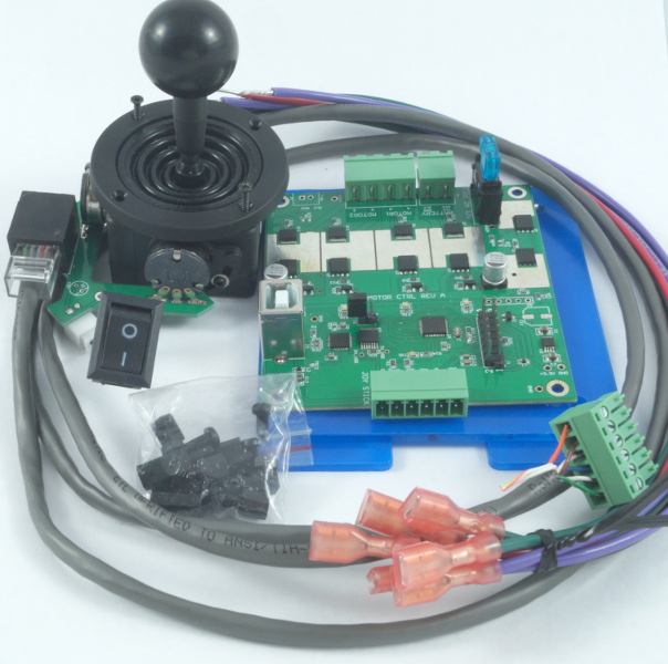
Figure 2. JOY-MOTOR-CTRL-KIT: Includes Joystick Motor Control board, Joystick with Joystick PCB Board, 3D Joystick enclosure, Power Switch, Ethernet cable, Battery and Motor Wires.
| Part Number | Description | Price | Purchase |
|---|---|---|---|
| JOY-MOTOR-CTRL-KIT | Joystick Motor Controller board Kit. See figure above to see what is included. | $179.95 |
Overview
We are using the Joystick and Motor Controller Board as the brains of the wheelchair that members of our foundation have collaboratively designed. It is under continual development, and we hope to further refine it over time.
All documentation for the board including schematics, assembly drawings and software is provided here so that you can build your own from scratch and make modifications, or you can purchase a unit form our website. Purchases of this experimental motor controller board help fund The Wheelchair Foundation.
Newer models have a
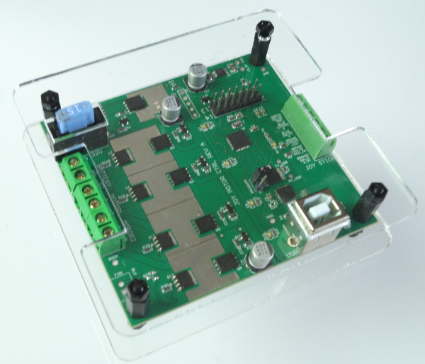
It is comprised of an H-Bridge PWM motor driver and microcontroller with software. It will read a 2 axis Joystick and convert those readings into appropriate motor movements. It has a USB port which can be used to update board settings such as the maximum speed, and to upgrade the firmware. It has 5 diagnostic LEDs, 4 of which indicate motor activity, and 1 which indicates a heart beat for indicating that the board is powered and operational.
The kit also includes a joystick board, which is soldered on to the joystick terminals. This board has an Ethernet plug, so you merely need to plug in the included Ethernet cable, and then wire the other end of the cable to the terminal blocks of the controller board. The power switch is also plugged into the joystick board. You will need to solder this board to the joystick.
We now include a black joystick enclosure in this kit. The joystick enclosure is a 3D printed part. You can use the supplied part, or print your own if you want it in a different color or finish. You can download the 3D STL file if you want to print it yourself: JoystickEnclosure.stl
Speed Control
There is a speed control knob on the latest version of the board. This can be turned to adjust the maximum speed of the chair. This should be set to a lower speed at first, and then as the child gets used to the chair, can be increased.
On older version of the board, this maximum speed is set through the USB port.
Assembly Instructions
The controller board has 3 terminal blocks that are used to connect wires to the other electrical components:
- TB1: Battery Inputs
- TB2: Motor Outputs
- TB3: Joystick inputs and outputs.
You can open the and close the terminal block terminals with a small flat head screw driver. Turning the screw clockwise will open the terminal, and counter clockwise will close the terminal.
If you are in doubt as to the position of pin 1 on a terminal block look at the back of the board, and you will see that pin 1 has a square ring around the hole. The board has text next to each of the terminals indicating the wire color and function of the terminal.
Left and right motors are referenced to the child's left and right if he/she where sitting in the chair.
Connect all of the terminal blocks using the following tables:
| TB1: Battery Inputs | ||
|---|---|---|
| Pin | Wire Color | Description |
| Pin 1 | RED | +12V, Battery Positive Terminal |
| Pin 2 | BLACK | GND, Battery Negative Terminal |
| TB2: Motor Outputs | ||
|---|---|---|
| Pin | Wire Color | Description |
| 1 | GREEN | Motor1 A-LEAD, Right Motor. |
| 2 | GREEN | Motor1 B-LEAD, Right Motor. |
| 3 | PURPLE | Motor2 A-LEAD, Left Motor. |
| 4 | PURPLE | Motor2 B-LEAD, Left Motor. |
| TB3: Joystick Inputs/Led Output | ||
|---|---|---|
| Pin | Wire Color | Description |
| 1 | SOLID ORANGE | 3.3V Output. Connects to both joysticks, and LED. |
| 2 | SOLID BROWN | Power On Input. Tie this to the power on switch. Tie to ground to turn on power to the board. If left untied to anything (floating) the board will be un-powered. |
| 3 | STRIPED BROWN | LED Output. This can be connected to an optional LED to indicate that the board is functional. |
| 4 | SOLID BLUE | Joystick Y input. Tie this to the middle pin of the joystick Y. |
| 5 | STRIPED BLUE | Joystick X input. Tie this to the middle pin of the joystick X. |
| 6 | SOLID GREEN | Ground. Tie this to GND. This connects to the GND pin of each joystick and to one side of the power switch. |
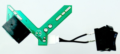
Figure 3. Joystick PCB Board
Follow these steps to wire up and verify the joystick and motor controller board:
- Plug in the power switch connector to the joystick board.
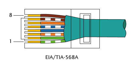
- Plug in the Ethernet cable into the corresponding socket on the joystick board.
- Wire up joystick controller according to the wiring diagram for TB3.
- Make sure the power switch on the Joystick enclosure is off.
- Wire up the battery according to the wiring diagram for TB1.
- Turn on the power switch.
- Verify that the heart beat LED is blinking.
- If it isn't blinking make sure that the polarity of the battery is correct.
- Make sure that the power on input (pin 2 on TB3) is tied to ground through the switch.
- If the heart beat LED is blinking rapidly, rather than once per second, recheck the wiring.
- Turn off the power switch, and verify that the heart beat LED stops blinking.
- Wire up the motorsaccording to the wiring diagram for TB2.
- For steps 9 through 13, tilt the wheelchair, or prop it up such that the wheels do not touch anything and can freely rotate.
- Turn on the power switch and verify that the motors are off. When the joystick is not pressed, the motors should be off.
- If the motors are on, verify that joystick is wired correctly.
- Press the joystick forward, and verify that both motors rotate in the forward direction.
- If they rotate in the wrong direction, reverse the polarity on their respective A/B leads. Note that changing the leads on the motor changes the direction of rotation.
- Press the joystick backward, and verify that both motors rotate in the backward direction.
- Press the joystick to the left, and verify that the left motor reverses, and that the right motor rotates forward.
- Press the joystick to the right, and verify that the left motor rotates forward, and that the right motor rotates backward.
- You are now ready to test the movement of the wheelchair, by setting it on the ground so that all 4 wheels touch. Run the wheelchair without anyone in it to verify that it is responding well to joystick commands.
- Calibrate the joystick via the USB port by running the 'c" command. See the following section for details on configuring the controller board via the USB port.
- The maximum speeds for forward, reverse, and rotate can be adjusted through the USB port. See the following section for details on configuring the controller board via the USB port. You reduce the maximum speeds if you are worried that it will go too fast.
Configuration Via USB Port
The controller board has a USB2.0 port which can be used to update motor settings, and firmware. When using the USB port remove all power and wires to it. Connect it through a USB hub to your computer.
A serial communications program must be used to access the board. While the board will work with most any serial communications program, we recommend Termie for Windows. If you are having difficulties, get it working with Termie first, then switch to your desired program.
When you plug a USB Comm device into your computer it will randomly assign a comm port number. To determine which comm port the device has been assigned to do the following:- Open Windows device manager. This can be access through the control panel.
- Plug in the USB device. You should see the device under the tree node labeled: "Ports (COM & LPT)"
- When you un-plug the USB device, that device should disappear. You now know the correct comm number.
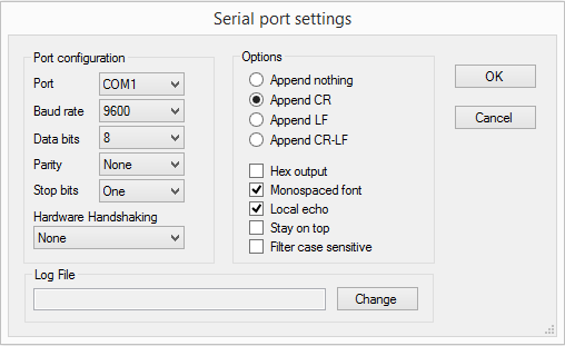
Now that you have the correct comm port number for the device, you can setup Termie:
- Open the Termie Program.
- Push the "Setting" button on the too bar.
- Select the comm port that you determined from the steps above.
- Set the Baud Rate to 9600.
- Data bits should be 8.
- Stop bits should be 1.
- Parity should be none.
- Flow Control should be none.
- Under the "Transmitted Text" group box, select "Append CR".
- Select Okay to close the Settings box.
- Put the cursor on transmit text line, at the very bottom, and type random text, and hit the enter key. The logger should respond with an error message. At this point you know that the settings are correct, and you can start sending correctly formatted commands.
- If you ever disconnect the USB port from the board, you will need to restart the USB connection in Termie, by twice pressing the large COMX button at the top of the terminal window.
With the exception of the COM Port, your Termie settings should look like the following screen shot:
| Commands | |
| h<CR> | Displays the help menu. |
| calibrate<CR> | Calibrate resting state of the joystick. Make sure the joystick is not pressed and is at rest before you run this command. |
| calibrateget<CR> | Get the joystick resting state calibrated offsets. |
| v<CR> | Displays the current software version. |
| l<CR> | Toggle enable or disable of the LEDs. |
| speeds<CR> | Get the current maximum speeds, as a percentage. Saved speeds may be slightly different than what was entered, due to how the numbers are represented internally. |
| speeds [forward],[reverse],[rotate]<CR> |
Set the maximum speeds. Numbers are in percent of the maximum possible speed. The square brackets denote fields, and are not used as part
of the command. Example: speeds 50,50,50; Sets all of the maximum speeds to 50%. |
Diagnostic (Heart Beat ) LED
The controller board has several LEDs: four of which indicate the directions of the motor, and 1 which is a diagnostic LED. When the board is correctly powered, the diagnostic LED should blink at a rate of about once per second. When there is an error condition, it will blink about 5 times per second.
The diagnostic LED will blink rapidly at 5 times per second under the following conditions:
- The USB cable is plugged in. When the USB cable is plugged in, the motors are turned off. To fix this condition, unplug the USB.
- The joystick is pressed away from the origin upon power up. To fix this condition, make sure that the joystick is free floating, and power cycle the power switch.
- One of the joystick wires has become loose or has broken. To fix this condition, do a visual inspection, or use an ohm meter or continuity tester to verify that the point to point connections are correct.
Troubleshooting
To trouble shoot you will need a low cost multimeter, which you can get from a hardware store, or www.amazon.com.
The diagnostic LED keeps blinking rapidly indicating an error state.
- Make sure you have removed the USB cable from the board.
- Read the voltage on the X and Y joystick inputs as follows:
- Connect the black lead of the probe to Terminal Block TB3-Pin 6 (GND) and the red lead to TB3-pin 5 (Joystick input X). The multimeter should read about 1.65V. If not then there is a problem with the cable.
- Connect the black lead of the probe to Terminal Block TB3-Pin 6 (GND) and the red lead to TB3-pin 4 (Joystick input X). The multimeter should read about 1.65V. If not then there is a problem with the cable.
- Try calibrating the joystick rest state via the USB. Use the calibrate command. See the "Configuration Via USB Port" section. After you are done calibrating it, make sure you remove the USB cable, and power cycle the power switch.
-
If the fuse is blowing, it could be the result of a mechanical problem such as the wheels being
too stiff to turn. The controller is meant to be used with small
children, and not for heavier loads. If there is too much weight
on the wheelchair it could also blow the fuse. We are using a
15A automotive fuse, but you could also try a 20A fuse. Never
short out the fuse as this could cause irreversible damage to the
controller board.
Firmware Upgrades Via USB Port
The controller can be updated with the latest firmware via the USB port, by downloading a executable file, using our update console program utility. This will be posted later when we have a firmware upgrade that we want to distribute.
If you want to develop your own custom code for the board see the software section below.
Detailed Design Documentation
Since our design is completely open, if you are curious and have good engineering skills you are welcome to look at our detailed design documentation. This will be beyond the skill level of the average wheel chair user.
3D Printed Parts
The joystick enclosure is 3D printed. The kit contains a black enclosure. You can download and print your own enclosure in any color you desire from this link: JoystickEnclosure.STL
The Open Wheelchair hardware design is licensed under CERN Open Hardware Licence v1.2 and the Software is licensed under the GNU General Public License Version 3. By viewing or using the design posted on this website you are agreeing to these licenses. To view the license see our license page.